Some time ago, I acquired an old but well-regarded mechanical filter from October 1990, operating at 500 kHz. While I don’t know its original intended use, I planned to use it as an IF filter in a simple HF transceiver. However, I wasn’t certain if its parameters were still within the datasheet specifications or if the filter was even functional after 34 years of unknown storage and usage conditions. To investigate, I decided to measure its characteristics using my NanoVNA
A Brief History of Mechanical Filters #
Mechanical filters like this one were widely used in early RF designs, especially in applications requiring narrowband filtering, such as single-sideband (SSB) radio or frequency division multiplexing systems. These filters offered precise frequency responses and high selectivity. However, mechanical filters are large, relatively costly, and require careful tuning. Another drawback is relatively low maximum frequency (< 1 MHz) witch makes it difficult to use in superhet receivers with one IF due to closely spaced (2 IF) mirror channel. Current advances in materials and technology led to the development of ceramic and SAW (Surface Acoustic Wave) filters, which are smaller, less sensitive to mechanical vibration, and easier to manufacture. While ceramic filters have largely replaced mechanical filters in modern RF systems, mechanical filters remain valuable artefacts for HAM radio enthusiasts.
Filter Specifications #
According to its label, ФЭМ2-045-500-2.75Н-3, and the datasheet for its family, this filter is a lower sideband (LSB) band-pass filter with a 2.75 kHz bandwidth at 500 kHz. The datasheet specifies:
- Maximum in-band loss: 20 dB (transmittance ~0.1)
- Ripple: ≤ 3 dB
- Load capacitance: 80–200 pF
- Load resistance: ~75 kΩ
This family of filters uses magnetostrictive transducers. Due to the high load resistance, the transducer coil includes a tap for easier matching with transistor circuits (as shown below). However, this reduces transmittance to about 0.01 – 0.05, significantly lower than the 0.1 specified for in-band performance

Impedance Matching with Resistors #
The NanoVNA has a 50 Ω input/output impedance, which is vastly smaller than the filter's 75 kΩ load resistance — a mismatch factor of 1500. To measure the filter’s parameters correctly, impedance matching is essential.
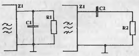
The datasheet recommends the matching network shown below (left), but I opted for a practical shortcut by transforming the parallel network into its series equivalent (right). This approach simplifies the calculations:

The transformed series impedance values are calculated as:
Assuming f=500 kHz (Δf/f≪1 so it is OK) , R1=75 kΩ and C1=90 pF:
- R2≈166Ω
- C2≈90 pF
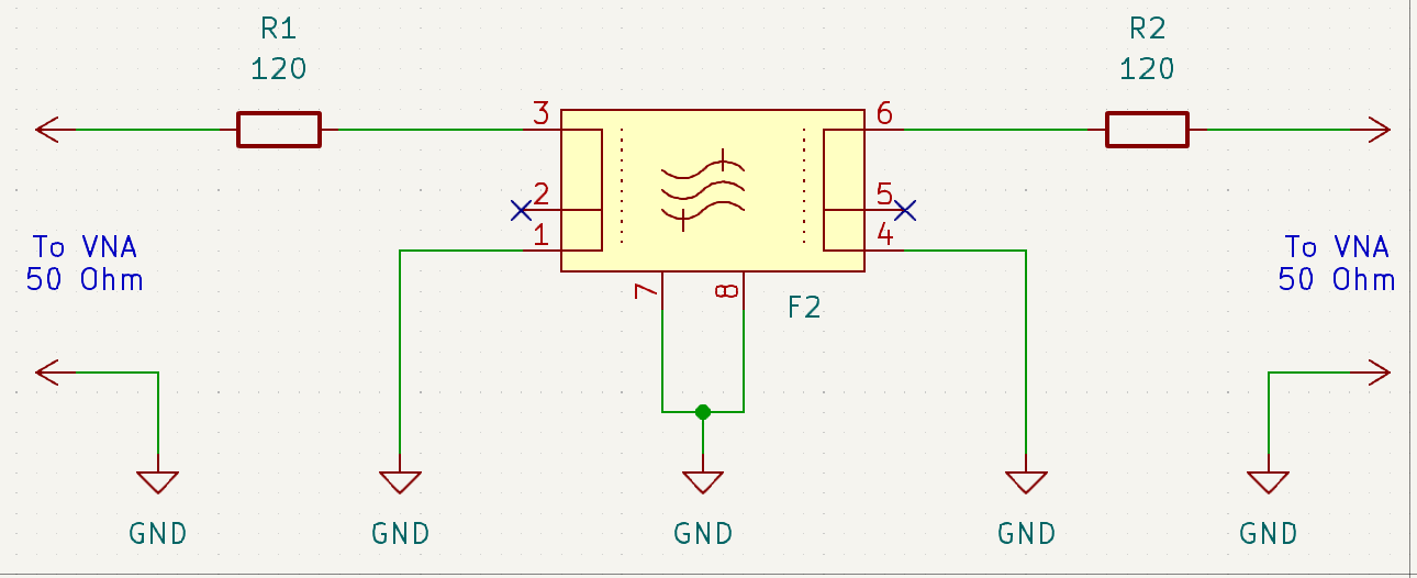
To further match 50 Ω to 166 Ω, I added a 120 Ω series resistor to each port of the VNA. The resulting network is illustrated below:

After assembling the network and performing initial measurements, the frequency response appeared as shown below:

The ripple in this initial response is significant, but don’t panic! This is due to the non-optimized load capacitors. After fine-tuning capacitors with a trimming screwdriver, the response improved significantly (turns out that the capacitance on the output side of the filter (S21 port of the VNA) plays a major role in the ripple suppression):

The updated frequency response shows:
- Insertion loss: ~31 dB
- Bandwidth: ~2.69 kHz (between -6 dB points at 496.95 kHz and 499.64 kHz)
- Ripple: ~2.5 dB
Transformer matching #
Resistor matching introduces coupling losses. The estimated losses (2 series 120 Ohm resistors) for the simple resistive network are:
where Z=50 Ω. Based on this, the real frequency response expected to be on 10 dB better. To improve coupling, I tested an RF transformer approach:

I used an autotransformer for simplicity. To match 50 Ω to 166 Ω, the turns ratio is:
The number of turns must also meet the rule of thumb for RF transformers: the primary winding’s impedance (looking into the source) should be at least four times the source impedance. At 500 kHz, the primary inductance should be:
I found a couple of coils with which gives
turns for the primary winding. (don't forget that
). For the secondary winding:
turns. With two such transformers, I measured the frequency response again. The improved coupling resulted in:

The response shows:
- Insertion loss: ~21 dB (taking into account +/- 1 dB losses in transformers this is close to the datasheet)
- Ripple: ~1.3 dB
Wrapping up #
Measuring high-impedance networks with low-impedance VNAs requires creative matching techniques:
- Resistor matching: A quick and simple solution that allows measurements but introduces significant losses (~10 dB).
- Transformer matching: Provides better performance but requires precise coil winding and careful design.
Despite its age, this 500 kHz mechanical filter performs within datasheet specifications and remains a viable option for future projects. I’m looking forward to incorporating it into an HF transceiver or similar design. Stay tuned for updates!
More information is available in full YouTube video at my channel:

