Qucs is a great and opensource tool to perform different electronic calculus such as circuit AC/DC analysis, optimisation, S-parameters, etc. In this article I will cover basic principles of AC and Transient analysis (basic QUCS simulations) on the example of resonant IF amplifier circuit.
Intro #
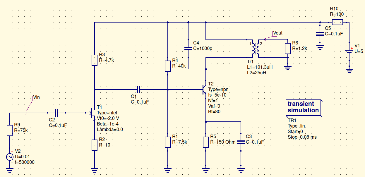
I needed an IF amplifier stage between IF filter and second mixer. The thing is that IF filter is electro mechanical one, and has about Z=72k output impedance. The good practice is not to load such filter on specified impedance, but let it work in underload regime, for example in order of 10Z for R load. The higer R load - the beter. Here comes JFETs with extremely low input impedance, but, unfortunatelly, unpredictable and low gain. Of course I could use OpAmp for that but it is not so interesting. So I decided to build 2 cascade amp, with first JFET-based cascade and second with BJT-based one. FInal schematic bellow:
Schematic description #
The IF frequency is 500kHz. IF goes on gate of N channel JFET. The working point of T1 is set by R2. R3 defines Vd point somewhere in V1(5v)/2 = 2.5V. (V1 - IdR3). Depending on transconductance (S) of T1, the gain of first cascade will be G1 = SR3, which in this simulation gives 2. (Here I consciously ommit minus sign in formula of G1 which shows phase change of the output signal on PI). After DC blocking capacitor C1, IF goes into common emmiter amplifier cascade. R4 and R1 defined base bias (around 0.6 volt), R5 defines current of emmiter and collector. The later one is short on V1 due to zero resistance of L1 in Tr1. C3 shunts R5 on working frequency leverages the overall gain. C4 and L1 creates resonant LC circuit with 500kHz resonant frequency. The load of this amp will be Tayloe mixer, with analog switch, that have 0.5-2.5k ON resistance, so in this model I choose 1.2k. With such parametrs the best performance (in terms of maximum Vout) will be with 1:4 transformer. Transient simulation in QUCS gives a nice picture for Vout:

AC analysis #
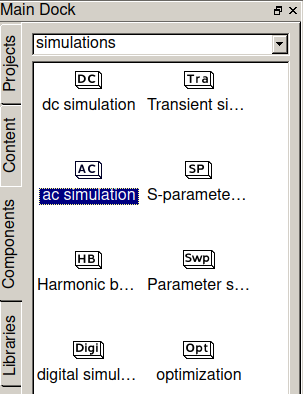
To perform AC analysis of this amp, lets choose AC simulation tool and DC simulation. Pay attention here, AC analysis needed DC simulation to be presented on schematic. Add it to schematic:
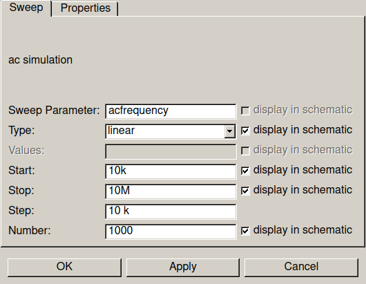
Set parametrs of simulation such as frequency range and type of change:
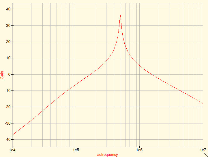
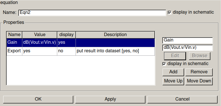
To be more visual, lets plot the Gain of amplifier. To do this, let's add an equation on schematic:
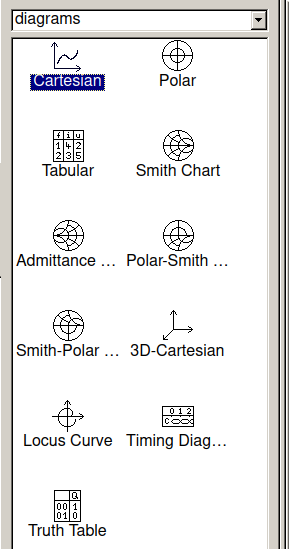
Press Simulate. After successful run, we can plot results. Let's add Cartesian plot on schematic:
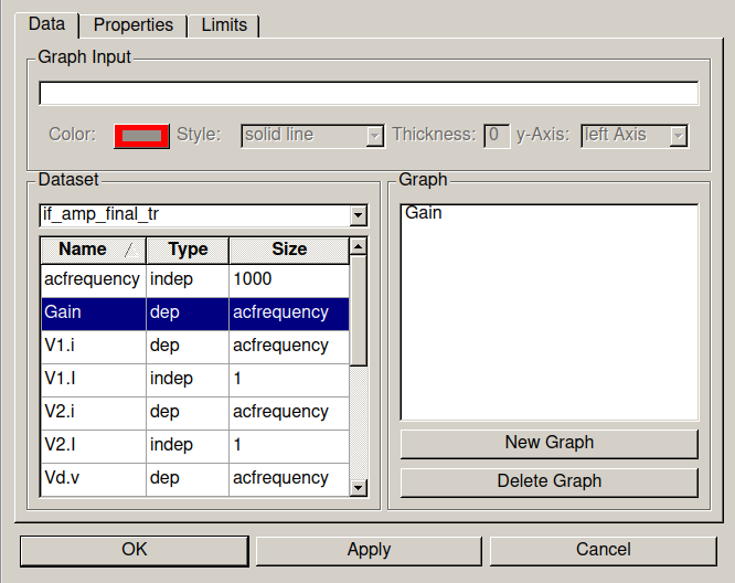
Select Gain among available variables:
And check "logarithmical X Axis Grid" on Properties tab. Now we have nice Gain vs Frequency plot: